|
|
 |
|
|
GWR Route: Banbury to Wolverhampton
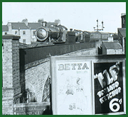
Solihull Station: gwrs1567
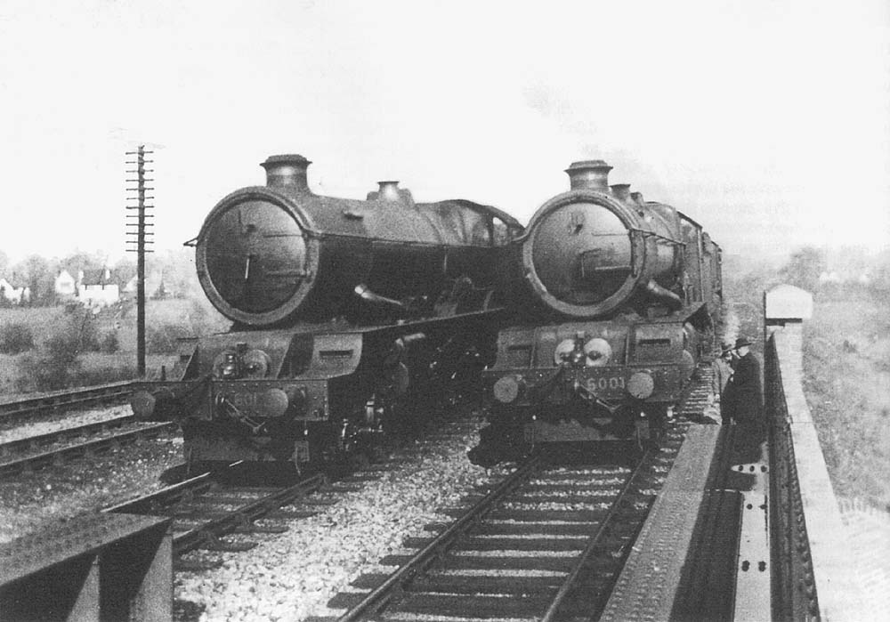
Dynamic testing of the new plate girder bridge over
Hillfield Road, halfway between Solihull and Widney Manor Stations. Four King
Class locomotives coupled in pairs and running side by side tested all of the
seventeen new bridges after the quadrupling of the track between Olton and
Lapworth was completed in May 1933. Here 6017 King Edward IV and 6005 King
George II are steaming in company with No.6001 King Edward VII and 6014 King
Henry VII. The 60XX King Class locomotive had a maximum axle weight of 22 tons
10cwt and with their tender, each locomotive had a total weight of
approximately 136 tons loaded.
At this time steel plate girder bridges were considered to
be the most economical and efficient type of structure for spans ranging from
15 to 80 feet. The normal arrangement was the ‘through floor’
arrangement where the bridge floor was carried on the bottom flanges of the
main girders as this maximised the road headroom beneath. The flooring system
was important as poor drainage could lead to corrosion of the steelwork. Here
what is termed a three girder, free flooring system was constructed with
regular cross girders at right-angles to and resting on the bottom flange of
the main girders. Two rail girders of similar size to the cross girders rested
on the lower flanges of each pair of cross girders, arranged so that each one
provided maximum support by being directly under the rails positions and
finally a steel plate floor was riveted above. One inch of asphalt was spread
over the plate floor to prevent water ingress and approximately four inches of
ballast laid above, on which conventional trackwork was constructed. This
produced a simple and economical arrangement with good structurally
capabilities, but was limited to double track spans of 36 feet and single track
spans of 60 feet.
The reason for these span limitations was that in order to
have sufficient structural strength, the main girder size needed to increase as
the span increased. Above these span lengths the typical height of the main
girder became so large that it infringed the Board of Trade clearance
requirement which stated that ‘No standing work is to be nearer to the
side of the widest carriage in use on the line than 2ft 4in and this at any
point between the level of 2ft 6in above the rails and the level of the upper
parts of the highest carriage doors’. This same regulation explains the
offset position of the bridge parapet on the outer side of the main girder.
 back back
|
|
|