|
|
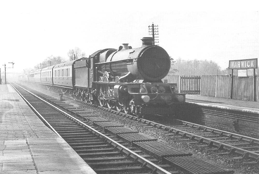
GWR Route: Banbury to Wolverhampton
Warwick Station: gwrw398
GWR 4-6-0 No 6015 'King Richard III is seen passing through
the station at speed at the head of an up express to Paddington circa 1930s.
Built at Swindon works to Lot 243 in June 1928 No 6015 remained in service
until September 1962 when it was withdrawn from Stafford Road shed in
Wolverhampton to be scrapped during April 1963 by Cox & Danks of Langley
Green near Oldbury. The King class was the final and most powerful development
of the GWR's 4 cylinder designs and were frequently seen on the Paddington to
Birkenhead services.
GWR CME (Chief Mechanical Engineer) Charles Collett's
Castles were arguably the GWR's finest passenger engine design, and on a
tractive effort basis, had proved themselves more powerful than LNER's Flying
Scotsman. Nevertheless, the advent of the Southern Railway's King Lord Nelson
class as the new leader in British express steam tractive effort (33,500lbs)
pushed the GWR's publicity office to push for one greater engine class, with a
nominal tractive effort of 40,000lbs.
Collett opted for smaller wheels on the King than his
Castles, after casting aside the conventional wisdom that large wheel diameter
was needed for the greatest speed. He had observed an express train being
overhauled by a mineral train hauled by a close-coupled GWR 4-8-0 with small
wheels. When compared with the Castle class, the slightly smaller wheels
adopted for the King Class allowed more space above them for a fatter boiler to
be built, as little extra engine height was available for expansion.
Nevertheless, such a reduction in wheel size was not without
its corresponding problems. A long standing Swindon design constraint imposed
by former CME George Jackson Churchward, was that the pistons would be level
and not slanted. This meant the centre height of the pistons would be the same
as the driving wheel axles. The smaller wheels thereby lowered the height of
the pistons. At the same time, to achieve the 40,000lb tractive effort, the
pistons were enlarged to 16¼” bore and 28” stroke. The outer
pair of pistons, acting on the centre wheels, needed to hang either side of the
rear wheels of the front bogie. The hidden inner pair of pistons, acting on the
front set of driving wheels, hung low between the front wheels of the bogie.
Both factors meant a traditional springing arrangement for the bogie was
impossible. A compromise design with the front wheels sprung on the outside and
the back wheels of the bogie sprung on the inside, produced the distinctive and
decidedly odd-looking long front bogie of the Kings. Courtesy of
6023 King
Edward II Project.
 back back
|