 |
|
Stations, Junctions, etc
Engine Sheds
Other
|

|
Miscellaneous: Operating Equipment & Practices
Miscellaneous Equipment: misc_equip193
Use the links below to access the following
images:
 |
Provision of water was a fundamental requirement when
operating steam locomotives and there was a comprehensive deployment of water
cranes distributed at strategic stations, engine sheds and important goods
yards along the railway routes. On the Great Western Railway main line in
Warwickshire water crane provision was made at; Leamington (8), Warwick (1,
later 2), Knowle & Dorridge (1), Tyseley (5), Bordesley (6), Moor St (3),
Snow Hill (7), Hockley (5) and Handsworth & Smethwick (1), while on the
North Warwickshire Line water cranes were provided at; Earlswood Lakes (2),
Henley in Arden (2), Bearley (1 - from Aqueduct) and Stratford-on-Avon (4). At
the end of both the Alcester and Shipston-on-Stow Branches, there were also
watering facilities. Additionally water troughs were also provided at
Rowington. It took time to fill a locomotive's tender or tanks with water so
the selected sites were usually locations where trains regularly started or
terminated their journeys, with intermediate locations providing back up. These
intermediate locations were normally selected because their proximity to
adequate water resources.
The whole system was designed to minimise the time it took
to replenish locomotives with the transfer of two thousand gallons of water
typically taking about five minutes. Large storage tanks were positioned where
they could gravity fed the water cranes through a large diameter pipe network.
The pressure depended upon the head of water in the storage tanks. The Great
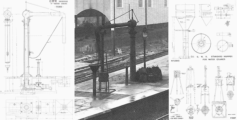
Western Railway standard water crane shown in official diagram No 2918 and seen
in the photograph of Moor Street station had an eight inch diameter horizontal
jib which could be swung to either side using a chain. A rod operated by a
lever on the main column locked the horizontal jib in place. The length of the
jib varied depending on location to allow the end to sit over the centre of the
track when it was swung out at 90 degrees (as this was the position of a
tender's central filler). This simplified the filling of tender locomotives,
but tank engines had their fillers off-centre, so it was only necessary to pull
the jib partially around. It was common place to find an arrow chipped into the
platform edge stone indicating where the ideal stopping place was. A steel
strut provided a rigid support for the horizontal jib from the main upright
column, but on longer jibs a second bracing strut at the rear of the column was
required. This bracing strut is not shown in the diagram but is evident in the
photograph. A six foot long flexible leather hose at the end of the jib was
provided to be placed into the locomotive's water tank or tender filler, before
the handle at the base of the water crane was turned to regulate the flow of
water.
Although a drain or grating was provided under where the
hose was positioned when it was not in use, to catch any dripping water, it was
later decided to supplement this with a raised hopper drain into which the end
of the hose could be placed when it was not being used. This raised hopper had
a top diameter of approximately 22 inches and can be seen both in the
photograph and in official diagram No 53913 above. As an added precaution
against the jib swinging, a hook was provided on the hopper's drain pipe on to
which the jib chain was attached when not in use. Note the original drawing
shows the chain attached to a hook on the main upright column.
The flexible hose was made from leather stitched with copper
rivets and this would hang flat when drained. It also had a tendency to freeze
solid in winter making the water crane unusable. To prevent the wet hose and
the crane's pipework from freezing, a fire grate (popularly referred to as a
fire devil) was provided. The fire grate can be seen in the photograph and the
component parts in official diagram No 43867 above. The fire grate was placed
adjacent to where the hose normally hung and the long fork-ended stovepipe
positioned to direct the heat on to the water crane's pipework.
Robert Ferris
back to
top
Standard GWR 8 inch Water Crane
back to
top
GWR Standard Hopper for Water Cranes
back to top
 back back

|
