Much of the information on this and other webpages of Warwickshire Railways is derived from articles or books listed in our 'bibliography'. Use the links below to access the following sections on this page:
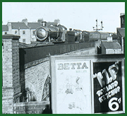
A brief overview of Birmingham Snow Hill StationThe Act of Parliament to allow the Birmingham & Oxford Railway Company (B&OR) to build their line from Oxford to Birmingham was passed on 3rd August 1846. The Act allowed the B&OR to utilise the London North Western Railway's (LNWR) Curzon Street facilities as its Birmingham station to be accessed via a viaduct linking from Bordesley. The B&OR's submission to Parliament was supported by the Great Western Railway Company (GWR) who subsequently purchased the company on 14th November 1846. However the LNWR, recognising the danger of the arrival of the the GWR and its intention of developing its network to the north to their own plans, therefore prevented the GWR's plans from coming to fruition. Faced with this hostility the GWR had no other alternative than to to build their own station. The route chosen into Birmingham reflected the ambitions of the GWR to continue onwards to Wolverhampton having purchased the Birmingham, Wolverhampton & Dudley Railway at the same time as the B&OR. This resulted in the railway crossing the centre of town partly in a tunnel, built by using the cut and cover method of construction, and partly in a deep cutting. The site selected for their station being the land originally occupied by the Oppenheims Glassworks. Originally known as Birmingham Station it was later known as Great Charles Street and Livery Street before the GWR finally adopted Snow Hill as the station's name in February 1858. The station was from the outset designed to accommodate mixed gauge trackwork which incorporated both standard and broad gauge within the station layout and configuration of pointwork. This was because any services using the lines to the north of the station had to use standard gauge tracks whilst to the south-east it had to accommodate broad gauge routes. The GWR had hoped to use the old Shrewsbury & Birmingham Railways powers to run over the Stour Valley line to Navigation Street (later New Street) but as with its original plan of sharing station facilities with the LNWR, the latter the company would have none of it and, after some astute work by the LNWR's lawyers, the GWR had no other recourse other than to build its own route to Wolverhampton. With construction of the new route commencing in 1851 the station operated as a terminus until 14th November 1854 when the new line through Hockley tunnel and on to Wolverhampton came into being. The line had been delayed because of a collapsed bridge over a road between Soho and Handsworth stations, the bridge having failed on the 26th August 1854, which was the day after which it had passed a Board of Trade inspection. The route to Wolverhampton initially served the intermediate stations of Priestfield, Bilston Central, Bradley & Moxley (opened later, June 1860), Wednesbury Central, Swan Village, West Bromwich, Handsworth & Smethwick, Soho & Winson Green, and Hockley. The station's opening was marked by the arrival in October 1852 of a broad gauge special train hauled by Daniel Gooch's Lord of the Isles locomotive. The initial building could not be described as being grand being a temporary timber structure which was to remain in place for another thirteen years until 1871 when the station was finally rebuilt. The temporary structure wasn't wasted by the frugal GWR as it was removed and reused at Didcot. The Great Western did however build in 1863 the ornate Great Western Hotel which fronted Colmore Row and which did provide an indication of the company's intent. The rebuilding of the station coincided with the full conversion of the mixed gauge trackwork to standard gauge (or narrow gauge as the GWR liked to describe it) in 1869. The layout of both the temporary station and the 1871 rebuild were essentially the same insofar that the through lines from Paddington to the Wolverhampton passed through the centre of the station served by two platforms. Services from the north terminating at Snow Hill were accommodated by bay platforms located at the northern end of both the up and down platforms. At the southern end of the station sidings were located which later were covered by the hotel and the roofing of the cutting in 1872. The 1871 rebuild was a much larger station but was still constrained by Snow Hill and Livery Street on either side and Great Charles Street at its northern end. The new station had a huge arched roof, with a simple wooden overhead bridge linking the two platforms in the centre of the platforms. Its design however was still not as grand or imposing as that built by the LNWR at New Street station. Access to the station for passengers arriving by road transport was provided via large station yards off both Snow Hill and Livery Street. Passengers wishing to transport their horse-drawn vehicles could do so as both the up and down platforms had carriage landings built adjacent to both yards. At the Wolverhampton end of the station, adjacent to Great Charles Street, a locomotive turntable was erected to facilitate the servicing of locomotives - Tyseley shed not being built for another thirty years. The signal boxes controlling the station were located at either end of the station with the South Signal Box being located between the rear of the hotel and the down platform and the North Signal Box being sited adjacent to Great Charles Street bridge on the up line. In 1872 the deep cutting running from Snow Hill station to Temple Row was covered over with the Great Western Arcade built over the top. The rebuilding of the third station commenced in 1906, which included incorporating a new pedestrian access from Colmore Row into the new booking hall, and was completed in 1912. The access was formed by creating a new entrance as part of the Great Western Hotel's facade, the hotel being taken out of public use and used as office accommodation. It was said that the noise and smoke of the trains passing underneath resulted in the hotel not being popular with guests. This time the GWR took up the challenge of competing with the now enlarged New Street station. The rebuilt station had a large booking hall with an arched glass roof and the platforms contained stylish buildings containing lavish waiting and refreshments rooms with oak bars of a standard worthy of many top hotels of the time. The GWR did not seek to enlarge the station by purchasing adjacent property as the LNWR did when they had enlarged New Street some twenty-five years earlier. This is probably because the GWR had, during the first decade of the new century, embarked on a major capital spending programme in building new lines, cutoffs to shorten journey times and new facilities such as Snow Hill station and money would have been very tight. Therefore the GWR resolved their need to expand the number of platforms and to provide more facilities not by widening the station but by extending the station beyond Great Charles Street which had for fifty years marked the northern limits of the station. The new layout adopted in the 1906 design utilised two island platforms, one for the each direction of travel, thereby allowing two through lines, one line on either side of the island platform. The two island platforms were separated by four roads, two up and two down with the centre roads allowing traffic to pass directly through the station without affecting the trains standing at the platforms. In addition, by creating platforms up to 1197 feet long, the platforms could accommodate two trains at the same time with trains arriving or departing from one half of the platform via scissor crossovers in the centre of the station. The GWR therefore adopted the practice of allocating a separate number to each half of the four through platforms. The through platforms were numbered: 1 & 2; 5 & 6; 7 & 8 and 11 and 12. At the Wolverhampton end of the station the previous configuration of a pair of bay platforms for each direction was continued and these were numbered 3 & 4 on the down side and 9 & 10 for the up bay platforms. The slope of the site from Colmore Row was utilised by employing the area beneath the station at Great Charles Street to be used to provide a parcels depot accessed via a driveway. Parcels and other goods being sent by passenger service were moved to each island platform via lifts located at the buffer stops of the bay platforms. The line towards Hockley was widened to four tracks to accommodate the increase in traffic. This option was not available to the south as the widening of Snow Hill tunnel would be very expensive requiring major land clearance. To accommodate the extra local traffic generated by the opening of the North Warwickshire line and the route to the South West, a new station, Moor Street, was built at the opposite end of the tunnel. During the 1960s the rebuilding of New Street station and the electrification of the West Coast mainline saw Snow Hill being used to accommodate the diverted traffic to London and Wolverhampton. However, once New Street was complete and the new electric services were operational the announcement that Snow Hill would be closed was made. All services were switched to Birmingham New Street and Moor Street. Express services were diverted to New Street from 1967. Local services north from Snow Hill to Wolverhampton Low Level railway station continued with four trains per day to Langley Green via Smethwick West using Class 122 units (nicknamed bubble cars) were the last to run and ended in March 1972. For a definitive history of Snow Hill station visitors should read Derek Harrison's book Salute to Snow Hill which whilst out of print is readily available in second hand book shops and libraries. Extract from correspondence in The Locomotive News and Railway Notes JournalVolume IX – No 55, published 10th June 1921To the Editor ‘LN&RN’ The Redevelopment of Birmingham Snow Hill StationExtract from Great Western Magazine Vol. XXIII. No.8,
August 1911
|
|||||||||||||||||||||||||||||||||||||||||||||||||||||||||||||||||||||||||||||||||||||||||||||||||||||||||||||||||||||||||||||||||||||||||||||||||||||||||||||||||||||||||||
| Exchange Location | Junction Lines | Exchange Lines |
| Birmingham | 6 | 18 |
| Bristol | 10 | 21 |
| Cardiff Goods | 5 | 10 |
| Exeter | 5 | 18 |
| Gloucester | 3 | 7 |
| Liverpool | 7 | 23 |
| Manchester | 4 | 12 |
| Newgate Street | 4 | 9 |
| Poplar | 4 | 6 |
| Paddington | 23 | 83 |
| Paddington Hotel | 5 | 160 |
| Paddington Goods | 6 | 14 |
| Plymouth | 7 | 23 |
| Swansea | 8 | 21 |
| Worcester | 3 | 5 |
Telephones: Birmingham District – Two new omnibus telephone circuits (worked on the common battery system for speaking and calling) have recently been introduced between Birmingham and Stourbridge, and Birmingham and Oxley. Magneto bells are employed, which are actuated by current derived from a vibratory generator fixed at Birmingham. The instruments are provided with two calling buttons, one of which will enable a station to call the exchange at Birmingham without interfering with intermediate stations on the circuit, while the other button is used for calling stations for omnibus service without effecting the exchange. It will be gathered that batteries are entirely dispensed with at the outlaying stations, while the advantages of the combined omnibus and exchange service are obvious.
Telephone Facilities – The telephone facilities on the Great Western Railway have been considerably increased in the past few years, facilitating train and traffic working, and the Directors have recently authorised the provision of the following:
Birmingham – A combination multiple switchboard giving access to both the railway and public telephone services with extension lines to all departments at Hockley and Birmingham stations. As a trunk line was already in existence between Paddington and Birmingham so this will give general intercommunication between these two places.
New Great Western Hotel for Birmingham.
The announcement that the Great Western Railway is to build a modern hotel at Birmingham (Snow Hill) station is yet another instance of the Company’s desire to provide the very best facilities for its travellers and the cities and towns it serves. The hotel is to be constructed on the site of the building now used as divisional offices and restaurant, and will have frontages in Colmore Row, Snow Hill, and Livery Street. The building is to be a six-floored, steel framed structure and will be faced with natural Portland stone. The facilities are to be of the most up-to-date nature and will meet a long-felt want in the City of Birmingham. The ground floor will comprise reception offices, hall, lounge, cocktail bar and cloak rooms; and the existing bar and grill room are to be improved. The first floor will be devoted mainly to public rooms, and will include a dining room with accommodation for 150 dinners, a spacious lounge and a smoke-room. In addition, there will be three private meeting rooms (which can be converted into a single dining-room with seats for 160 people), and display and stock rooms in which business houses can entertain their customers and hold trade shows.
The first floor will also accommodate the kitchens. The remaining five floors of the new hotel will contain the bedrooms, numbering in all 28 double rooms and 142 single – each with a bathroom and lavatory. There will also be a private suite on each of these floors. Central heating, and air-conditioning of the main public rooms, will add to the comfort of patrons, and fire-proof floors will conduce to their safety. The main hotel entrance will be in Colmore Row, and there will be direct access to the booking hall forecourt on the station. New divisional offices and accommodation for the hotel and refreshment rooms staff will complete the rebuilding scheme. Work is to start this year and, when completed, will convert Snow Hill station into one of the most imposing railway structures in the provinces.
.....................................................................
For the purpose of intimating to Enginemen of Down Trains passing through Snow Hill Tunnel that they are nearing the North End of the Tunnel, a Clapper has been fixed on the Down line side about 150 yards from the Snow Hill end of the Tunnel, which is operated by means of a treadle. Every pair of wheels passing over the treadle will sound the Clapper.
Should the Driver of a Down Train notice any defect in the working of the apparatus, he must inform the Station Master or Platform Inspector at Snow Hill station, if necessary stopping specially for the purpose.
In connection with the track circuit on the Down Line through Birmingham (Snow Hill) Tunnel, special apparatus has been provided to enable the Signalman to restore the track circuit to its normal ‘clear’ condition in the event of a train (coming out of the Tunnel) failing to do so owing to the presence of sand on the rails.
The apparatus consists of a special key box fixed in the South Box, in which a key stands normally locked.
In the event of a train coming out of the Tunnel and failing to cause the track circuit indicator to show ‘clear’, the key in the key box will be automatically freed. In such circumstances, the Signalman is authorised to withdraw the special key in accordance with the instructions which are cast on the box, and AFTER HAVING SATISFIED HIMSELF THAT THE DOWN LINE IS CLEAR OF TRAINS OR VEHICLES, he must withdraw the key and insert it in another key box which is also fixed at the South Box, and turn the key to the right as far as it will go and then turn the key back again and withdraw it.
This action will have the effect of restoring the track indicator to the ‘clear’ position, but before the signalman can again peg ‘line clear’ on the Down line block instrument, it will be necessary for the key to be replaced in the key box in the South Signal Box and locked therein.
In every case of failure, whether the use of the key in the manner above described is effective or not, the Telegraph Linesman must be immediately sent for in order that he can take steps to see that the rails are clear of sand, or any other necessary action.
To facilitate the shunting operations in Snow Hill Tunnel, an electric bell is provided in the South Signal Box, which when operated by push buttons fixed on the Tunnel wall on the Up side to be worked by the Shunters, and the following code must be observed:-
- Turn Points backing from Up Main … 1 ring
- Turn Crossover road points in Tunnel … 3 rings
The Shunter will be responsible for verbally instructing
the Signalman as to which road it is required to shunt back to, the bell code
being established to indicate that vehicles are over the points inside the
Tunnel which it is necessary to work.
For the purpose of intimating to Shunters performing shunting operations in the tunnel sidings on the Down side at Birmingham South, when the points are set for a down train to run from the Down Main Line to either No. 1 Platform Line or No. 5 Platform Line and Down Main Line, a Lamp Indicator containing two lights – one red light and the other a white light – and facing towards the Tunnel, is fixed on the sixth column from the South Box in the direction of the Tunnel.
The exhibition of the Red light in the Lamp Indicator will indicate that the points are set for a train or engine to run from the Down Main to No. 1 Platform Line, and the exhibition of the White light will indicate that the points are set for a train or engine to run from the Down Main to either No. 5 Platform Line or the Down Main Line.
The Lamp Indicator is provided for the guidance of Shunters and others performing shunting operations in the Down Tunnel Sidings to ensure safe working and must be closely observed by all concerned, and all movements must be kept well clear of the line for which the Indicator shows the points in the Down Main Line have been set.
One of the two lights in the Indicator should always be showing towards the Tunnel Sidings, but if from any cause no light is visible, the Shunter must act in the same way as if the Red light were showing and also immediately report the absence of a light to the Station Master or Platform Inspector. (A. 9758.)
Enginemen of Up Goods Trains not requiring to stop at Moor Street must stop dead at Moor Street Up Distant Signal (fixed as lower arm on Birmingham South Up Starting Signal in the Tunel) unless the Distant Signal is in the ‘All right’ position. After stopping in the manner described, the train may proceed cautiously to Moor Street provided the Starting Signal for Birmingham South is in the ‘All right’ position.
Enginemen of all Up Goods Trains having traffic for Moor Street must stop dead at Birmingham South Box and inform the Signalman the Train has traffic off at Moor Street and must run to the Up Relief Line. When this has been done, the train can proceed, provided the proper Signals are lowered, but it will not be necessary for the Enginemen to stop a second time as laid down in the foregoing paragraph.
When an Up Goods Train is about to leave Snow Hill and has to call at Bordesley Goods Station to put off traffic, the Engineman must stop at Birmingham South Box as per instructions on page 17 and the Signalman in the South Box must advise the Signalman at Bordesley North of the fact that the Train then leaving has to call at Bordesley.
The Section between these Boxes is worked as
under:-
Nos. 1 and 2 Down Platform Lines under the Standard Block
Telegraph Instructions, with the following Clearing Points:-
| CLEARING POINTS - DOWN LINE | |
| SOUTH BOX | When ‘Line Clear’ has been received from North Box |
| NORTH BOX | No. 2 platform line down home signal |
When a Horse Box, Carriage Truck or any other Vehicle is left on Nos.1 or 2 Down Platforms the Shunter detaching or placing such a Vehicle on the Line will be responsible for advising the South Box Signalman, and after dark, seeing that a Red light is exhibited at each end.
Route Indicating Instruments are also provided; for method of working see General Instructions \Clause 17, page 141.
When Nos. 5 and 6 Down Platform, Down Main, Up Main and Nos. 8, 7, 12 and 11 Up Platform Lines are unoccupied, the Section must be worked under the Standard Block Telegraph Instructions with the following Clearing Points:-
| CLEARING POINTS | ||
| Down Line | Up Line | |
| SOUTH BOX | For all Passenger trains stopping at Bordesley, Light Engines, Empty stock and Ordinary Goods Trains. When the Line on which Train is to run is unoccupied to Starting Signal. | Up Starting Signal in
Tunnel. The Warning Signal 3-5-5 (Regulation 5) may be sent from the South Box to the North Box for Up Trains |
| For all Express Passenger
Trains not booked to stop at Bordesley, but stopping at Birmingham, and for
Passenger and Express Trains not booked to stop at Birmingham. When the
Line on which the Train is to run is unoccupied to the North Box Home
Signal. NOTE. Engine or Engine and Brake may be accepted from the rear under the warning arrangement when Line is clear to South Signal Box. The Warning Signal must only be used when the Facing Points at the South end of the Station are set for the Down main Line. Only one Engine or Engine and Van on the Down Line must be allowed to leave the Box in the rear for Birmingham (Snow Hill), under this ‘Warning Signal’. The ‘Warning’ must not be used for two or more Engines coupled together. |
Before an Up Passenger Train (not stopping at Birmingham) is allowed to leave the North Box and run through the Up Main Line, an assurance must be given to the Signalmen at the North and South Boxes by the Platform Inspector that the up main line is clear as between the North and South Signal Boxes. | |
| NORTH BOX | For all Passenger Trains booked to stop at Birmingham and Ordinary Goods Trains. When the Line is unoccupied to the Down Home Signal for Line on which the Train has to run. | For Up Non-stopping Passenger and Non-stopping Goods Trains. When Line is clear to Up Starting Signal |
| For Non-stopping Passenger and Non-stopping Goods Trains. When the Line is unoccupied to the Starting Signal for Line on which the Train has to run. | For Up Passenger Trains booked to stop at Birmingham and Ordinary Goods Trains. When line is clear to Inner Home Signal for Main Line, and North end of Scissors Crossing for Relief Line. | |
1. Sending ‘Is Line Clear?’ Signal. – The ‘Is Line Clear?’ Signal must be sent as under:-
| SOUTH BOX | Down Line | When ‘Is Line Clear?’ is received from the Signal Box in rear, if ‘Train out of Section’ has been received from North Box for previous Train. |
| Up Line | About one minute before the Train is ready to start. | |
| NORTH BOX | Down Line | About one minute before the Train is ready to start. |
| Up Line | When ‘Is Line Clear?’ is received from the Signal Box in rear, if ‘Train out of Section’ has been received from South Box for previous Train. |
2. (a) The Up Scissors Crossing Signals, situated just north
of Great Charles Street Bridge, and the Stop Signal at North end of No. 12 Up
Platform, are the Starting Signals for the North Box. The North Box is entitled
to send a Train as far as these Signals without signalling to the Box in
advance.
(b) The Down Platform Scissors Crossing Signal situated just
north of Great Charles Street Bridge, must be regarded as No. 5 Down
Platform Starting Signal for the South Box, and the Down Main Scissors
Crossing Signal as the Down Main Advanced Starting Signal for the South
Box. The South Box is entitled to send a train as far as these Signals without
signalling it to the Box in advance. The Stop Signal, suspended from the
station roof, to protect the Crossover Road between Up and Down Main Lines
south of Great Charles Street is the South Box Down Main Starting
Signal.
(c) No. 7 Up Platform, No. 11 Up Platform and Up Main Stop
Signals situated nearly opposite the South Box, are the Up Home Signals for the
South Box.
(d) The Stop Signal at the North end of No. 2 Down Platform,
the Stop Signal at the North end of No. 6 Down Platform, and the Down Main Stop
Signal near the North end of No. 6 Down Platform Line are the Down Home Signals
for the North Box.
(e) Calling-on Arms are fixed upon the South Box Up
Home Signals, and are to be used for Shunting purposes only, and Enginemen must
be prepared to stop short of any obstruction. The following special
instructions must be observed in working Trains through No. 11 and No. 7 Up
Platforms and Up Main Lines.
(f) The Signalling is so arranged that the
Up Starting Signal in the Tunnel must be lowered before No. 11 or No.7 Up
Platform Lines or Main Line Home Signals can be lowered, and the lowering of
the Platform Lines or Main Line Home Signal will be an indication to the
Enginemen that the Up Starting Signal in the Tunnel is also at the ‘All
Right’ position, and that the road is clear for him to proceed on his
journey.
(g) When a Train is detained at either of the South Box Up Home
Signals referred to, Enginemen must, when either Up Home Signal is lowered, act
in accordance with Rule 45, clause B.
3. The Down Distant Signal for the South Box must be lowered when the Line on which the Train is to run is unoccupied to the Down Starting Signal for the South Box, but drivers must be prepared to find the Down Starting Signal for the South Box at ‘Danger’.
4. When an Up Passenger Train is turned on to Nos. 3, 4, 9 or 10 Bay Lines, unless the Lines on which the Train is to run is clear to the Stop Block, the Train must be stopped dead, and the Calling-on Arm lowered for Enginemen to draw forward.
5. Vehicles may be shunted outside the Down Home Signal at the South end, and the Up Home Signals at the North end. Paragraph ‘E’ of Regulation 13 of the Block Telegraph Instructions must be carried out.
6 (a) Snow Hill Tunnel – Regulation 9 for Signalling
Platelayers’ Trollies will apply. When a Platelayers’ Trolley goes
through on the Down Line, a Permanent Way Flagman must be stationed at Moor
Street Down Starting Signal until the Trolley has cleared the
section.
(b) Regulation 25 will not apply between Birmingham South and
Moor Street. All trains to be piloted through the Tunnel in case of failure of
Block and Speaking instruments.
7. When the ‘warning’ signal 3-5-5 (Regulation 5) is received from the South Box for an Up Train it will not be necessary to stop the train dead at the Home Signal for the North Box, and again at the Box, but the Home Signal must be kept at ‘Danger’ until the Train has been well checked, when the Home and Calling-on Signals may be lowered.
The following modifications and additions to the General Regulations will also apply:-
| Additional Bell Signals | Beats on Bell | How to be given |
| Engine with odd Vehicles in right direction for
shunting purposes Train setting Back in wrong direction Train set Back in wrong direction removed, and Line now clear Train set Back in wrong direction now come to a stand Train set Back in wrong direction cleared at the Box in the rear Shunting into Forward Section Forward Shunt withdrawn Train last signalled incorrectly described |
4 8 7 10 7 8 8 8 |
1 – 3 2 – 3 – 3 2 – 5 3 – 3 – 4 5 – 2 3 – 3 – 2 consecutive 5 - 3 |
8. Admitting Trains one behind another if Section is already occupied.
(a) When a Train or Engine is already in the Section and another Train or Engine is required to be sent forward into the Section, the Signalman must give the ‘Is Line Clear?’ Signal to the Box in advance, and the Signalman there will reply by one beat on the Bell, and upon this reply being received, the second Train or Engine may be allowed to enter the Section. It will not be necessary to give the ‘Call Attention’ Signal before the ‘Is Line Clear?’ Signal in such cases. When the Train or Engine is allowed to pass, the ‘Train Entering Section’ Signal must be given; the Signalman receiving it will acknowledge it by one beat on the Bell and will move the Disc forward one number.
(b) As each Train or Engine passes out of the Section, the Bell Signal, 3 beats (thus, 2 – 1) must be given to the Box in rear, the Block Indicator remaining at ‘Train on Line’ and the Disc must be moved back one number, so that the actual number of Trains in the Section may be shewn. The Signalman at the Box in the rear will acknowledge the Signal (2 – 1) by one beat on the Bell. When the last Train has passed out of the Section, in addition to giving the Signal (2 – 1) on the Bell the Discs and Indicator must be placed in the normal position, which the Signalman in the rear will acknowledge by one beat on the Bell.
9. Up Main and Up Platform Lines.
(a) Before an Up Passenger Train is allowed, under these Regulations, to enter the Section whilst the Indicator from the South Box shows ‘Train on Line’ it must be brought to a stand at the Outer Home Signal, and the Signalman must, after bringing the Train to a stand, lower the Signal to allow the Driver to draw up, and after the Train has been brought nearly to a stand, the Up Inner Home Signal may be lowered, and the Train allowed to draw cautiously forward, and after being checked at the Starting Signal, the Calling-on Arm may be lowered for the Train to draw behind the one already in the Section.
(b) Before an Up Goods Train or Light Engine is allowed under these Regualtions to enter the Section whilst the Indicator shows ‘Train on Line’ it must be brought to a stand at the Up Starting Signal, and after being stopped dead, the Calling-on Arm may be lowered for the train or Engine to draw behind the one already in the Section.
10. Down Main and No. 6 Down Platform Lines – Before a Down Train or Engine is allowed, under these Regulations, to enter the Section when the Disc from the North Box shows ‘ Train on Line’ it must be brought to stand at the South Box No. 5 Down Platform Starting, or Down Main Advanced Starting Signal as the case may be, and the Calling-on Arm then lowered for the Engineman to draw forward.
11. Setting Back in Wrong Direction.
(a) Should it be necessary to set back a Train, Engine or Vehicle in the wrong direction outside the Home Signal, the ‘Setting Back’ Signal, 8 beats (thus, 2 – 3 – 3), applying to the Line which it is required to block, must be sent to the Box in the rear, and no Train, Engine or Vehicle must be allowed to set back outside the Home Signal until the proper reply giving permission, 8 beats (thus, 2 – 3 – 3) has been received. When permission has thus been obtained the Indicator for the Line about to be blocked must be placed at ‘Train on Line’. After having given permission in this manner for the Line to be blocked, the Signalman at the Box in the rear must not allow any Train, Engine or Vehicle to enter the Section until he receives the Bell Signal (2 – 5), denoting that the obstruction has been removed and the Indicator is placed in its normal position, or until he receives the Signal 10 beats on the bell (thus, 3 – 3 – 4), which indicated that the Train, Engine or Vehicle which was set back has come to a stand; and upon receipt of that Signal he may let another train, Engine or Vehicle into the Section under the Instructions in Clauses 8(a), 9(a) and (b) and 10. The Signals (2 – 5) and (3 – 3 – 4) must be acknowledged by repetition. Should it be necessary for the Train, Engine or Vehicle setting back in the wrong direction to go through the Section and be withdrawn by the man in the rear, the Engineman must be verbally instructed, and when the Signalman in the rear has cleared the Line at his end he must give the Signal (5 – 2) on the Bell to the Signalman in advance to denote that the obstruction has been removed, and the latter must acknowledge by repetition, and, when permissible, place the Indicator in its normal position.
(b) The Signal (2 – 3 – 3) must not be acknowledged by the North Box Signalman if the Signals are ‘Off’ for a Train to approach on the Line it is required to obstruct and no Train must be allowed to pass the Up Outer Home Signals for the Line on which the train is setting back until latter has come to a stand, but Trains may be allowed to run to the Bay Lines. Should an Engine or Train be already standing at the North Box Up Starting Signal the Ground Signalman must be advised to Instruct Engineman not to move until Train, Engine or Vehicle setting back has come to a stand.
(c) The Signal (2 – 3 – 3) must not be acknowledged by the South Box Signalman if permission has been given of any Train to approach on the Line it is required to obstruct, nor must the ‘Is Line Clear?’ Signal be acknowledged for any Train from the Box in rear if permission has been given for a Train, Engine or Vehicle to set back in the wrong direction from the North Box unless the Points are set for the Down Train to run over the Down Main Lin, and the Train from the North end is running in the wrong direction over No. 5 Platform Line and the Tunnel Siding Points at South end of Station are set for that Siding; or if the Down Train is running over No. 1 or No. 5 Platform Lines unless the Train, Engine or Vehicle setting back in wrong direction is on Down Main Line and the Points are set to turn it to the Up Main Line either at South end of Great Charles Street Bridge or opposite the South Signal Box. Should however, a Train or Engine be already standing at the South Box Down Starting Signal, the Ground Signalman must be advised to instruct Engineman not to move until Train, Engine or Vehicle setting back has come to a stand.
12. Shunting into Forward Section.
(a) When it is necessary for a Train or Engine to go into the forward Section for shunting purposes and to be afterwards withdrawn in rear, the Signal, 8 beats (thus 3 – 3 – 2), must be sent to the Box in advance, and no Train or Engine must be allowed to enter the Section in this manner until the Signal has been repeated, or acknowledged by one beat on the Bell (see next paragraph) by the Box in advance, and the Indicator of the Block Instrument for the Line affected placed to ‘Train on Line’ if not already in that position.
(b) Should the Line be already occupied, the Signalman receiving the Signal 3 – 3 – 2 must not repeat it to the Box in rear, must reply by one beat on the Bell, and move the Tell-Tale Disc forward one number, and the Signalman in the rear must stop the Driver of the shunting Train in accordance with the Instructions in Clauses 8(a), 9(a) and (b) and 10.
(c) When the ‘Shunt’ is removed at the Box in rear, the Signalman must give the ‘Forward Shunt Withdrawn’ Signal 8 beats consecutively, to the Box in advance, and this must be acknowledged if the Section is clear by the Indicator of the Block Instrument being placed in its normal position; but should the Section be still occupied in advance of the Shunt, the Signalman in advance must move the Tell-Tale Disc back one number.
(d) When a Train or Engine which has been signalled forward by the code 3 – 3 – 2 is required to go through the Section, the Signal ‘Train last signalled incorrectly described’ (5 – 3) must be given to the Box in advance and, on that Signal being acknowledged by repetition, the Train or Engine must be correctly signalled on the Bell, the Disc remaining at ‘Train on Line’ position.
13. Working of Trains Through Scissors Crossings. – The line through the Sissors Crossings must only be used as under:-
(a) A Man is employed on the Gantry Bridge at the Scissors Crossings near Great Charles Street Bridge, who is in Telephone communication with the North and South Boxes. The points of the Scissors Crossings must not be turned by the Signalman except on authority from the Gantryman by telephone, and before giving such authority, the Gantryman will be responsible for seeing that any Train standing ahead of the Points is clear and must have assurance from the Station Master or Platform Inspector that the Train will not be moved in the wrong direction until the approaching Train has passed through the Scissors Crossing or come to a stand.
(b) When Trains are sent from the Platform Line to the Main Line and from the Main Line to the Platform Line through the Scissors Crossing, they must be signalled on the Bells and Discs applicable to the Line on which the Train will pass after it has gone over the Scissors Crossing, and not upon the Instruments applicable to the Line on which the Train approaches the Scissors Crossing.
14. Vehicles left on Main or Platform Lines. – If a Horse Box, Carriage Truck or any other Vehicle is left on the Main or Platform Lines, the duties of advising the Signalman will rest on the Men as under:-
(a) Down Lines.
If left ahead of South Box
Starting Signals the Gantryman must advise the North Box Signalman who, if the
Block Instrument is not standing at the ‘Train in Line’ position,
must immediately send the ‘Blocking Back Outside Home Signal’ (3
– 3) to the South Box, and place the Block Indicator to ‘Train on
Line’.
If left in the rear of these Signals, the Shunter detaching
the Vehicle must advise the South Box.
(b) Up Lines.
If left in advance of the North
Box Starting Signals the Gantryman must advise the South Box Signalman who, if
the Block Instrument is not standing at the ‘Train on Line’ position,
must immediately send the ‘ Blocking Back Outside Home Signal’ (3
– 3) to the North Box, and place the Block Indicator to ‘Train on
Line’.
If left to the rear of these Signals, the Gantryman must
advise the North Box Signalman.
When a Horse Box, Carriage Truck, or any other Vehicle is left on Nos. 12 or 11 Up Platform Lines the Shunter detaching or placing such Vehicles on the Line will be responsible for advising the Gantryman, who must advise the Signalman at both North and South Boxes.
15. Shunting Vehicles on to or off the rear of down trains at south end. – When it is necessary to shunt vehicles on to or off the rear of Down Trains at the South end, the Tunnel Siding must , whenever possible, be used as a Shunting Neck, but when this is not possible, an Engine must be attached to the Vehicles at the Bordesley end, and the Vehicles may then be shunted to Down Main Line instead of having to cross over to the Up Main Line.
16. No. 7 Up Platform Line – Enginemen of trains running to No. 7 Up Platform Line, must draw up as close as practicable to No. 7 Line Home Signal in order to avoid stopping short of the bridge, where the smoke and steam are dispersed under the roof and cause deterioration of the steelwork and corrugated iron sheeting.
17. Electric Route Indicating Instruments.
(a) Down Trains between South and North Boxes. – To inform Birmingham North Box the direction of Train about to be signalled, an Indicating Instrument, pegged at Birmingham South and keyless at Birmingham North for Down Line Working is provided; the peg to be inserted to the required indication preceding the proper ‘Is Line Clear?’ code, as under:-
| Down Main | Nos. 5 and 6 Down Platforms | Nos 1 and 2 Down Platforms |
| To Snow Hill Station only | To Snow Hill Station only | To Snow Hill Station only |
| To Stourbridge Branch | To Stourbridge Branch | To Stourbridge Branch |
| To Wolverhampton Line | To Wolverhampton Line | To Wolverhampton Line |
| To Hockley Yard | To Hockley Yard | To Hockley Yard |
| To Up Sidings | To Up Sidings | To Up Sidings |
| To Down Sidings | To Down Sidings | To Down Sidings |
| From North Warwickshire Line | From North Warwickshire Line | From North Warwickshire Line |
| From Main Line | From Main Line | From Main Line |
(b) Up Trains between North and South Boxes. – Similar instruments have been provided for Up Line Working between Birmingham North and South Boxes, pegged at the North Box and keyless at the South Box, showing the following indications:-
| Up Main | Nos. 8 and 7 Up Platforms | Nos. 12 and 11 Up Platforms |
| To Snow Hill Station only | To Snow Hill Station only | To Snow Hill Station only |
| To Bordesley Junction only | To Bordesley Junction only | To Bordesley Junction only |
| To Tyseley Yard | To Tyseley Yard | To Tyseley Yard |
| Through Train | Through Train | Through Train |
| To Tunnel Sidings | To Tunnel Sidings | To Tunnel Sidings |
(c) The method of operating the instrument is as
follows:-
(i) After giving ‘Call Attention’
Signal and before asking ‘Is Line Clear?’ for the Train concerned,
the Dial Peg must be inserted in the hole opposite the words describing the
route, and the sliding bar at the right-hand side pulled fully out, which when
released will cause the needle in the receiving dial of the instrument at the
opposite end of the section to rotate to the corresponding
description.
(ii) The instrument must be left in this
position until ‘Train out of Section’ is received for the Train
concerned (unless the Section is occupied as shown in Clause iii) when the Dial
Peg must be withdrawn, which will cause the needle of the receiving dial of the
instrument at the opposite end of the Section to move on to the normal position
of zero.
(iii) When the Section is already occupied
and it is necessary for another Engine or train to be signalled, the Signalman
at the rear must unpeg Indicating Instrument and before giving the ‘Is
Line Clear?’ Signal for the second or subsequent Train must indicate the
direction of the Train about to be signalled, so that the last Train in the
Section will be shown on the Indicating
Instrument.
(iv) In the event of the needle stopping
short of zero when returning to the normal position the Signalman must press
the small adjusting button placed above the receiving dial of the instrument,
which will cause the needle to travel to its normal
position.
(v) Directly the Dial Peg is inserted, and
the slide is withdrawn, the Zero Cross on the transmitting portion of the
instrument falls, and a red disc takes its place, showing the Signalman that
the instrument has operated; and when the peg is withdrawn the Zero Cross
should return to its normal position, which is an indication that the
instrument is again in a position for sending signals.
18. Foggy Weather
(a) In foggy weather or during falling snow, it will be the duty of the Fog-Signalman to walk through the Station and see that the Lines are clear up to the points mentioned in these instructions.
(b) Each Signalman must obtain an assurance from the Fog-Signalman attached to his Box that the Line is clear to the specified clearing point before giving the necessary signal to admit a Train into the Station.
(c) Up Trains running to the Bay Lines must be stopped dead at the Inner Home Signal and the Driver verbally instructed to which Platform he is running.
(d) When it is necessary for a Train to enter a Section already occupied, the Train must be stopped dead at the North Box Up or South Box Down Starting Signal as the case may be, and the Signalman must telephone the Ground Signalman to instruct the Enginemen exactly what is required and after an assurance is obtained from the Ground Signalman that this has been done the Signal may be lowered for the Train to draw up, provided the necessary Block Telegraph Signals have been exchanged.
19. Electrical Bell and Hooter between Signal Boxes and the Platforms. – The Signalman in the South Box must ring the Electrical Bell fixed on the Down Platform on receipt of ‘Train entering Section’ Signal from the rear:
- For Passenger Trains to Nos. 1 and 2 Platforms … Once
- For Passenger Trains to Nos. 5 and 6 Platforms … 2 rings consecutively
- To call attention of Station Staff … … Continuously
The Signal man in the North Box, in like manner, must sound the Hooter on the Up Platform on the trains leaving Hockley:
- For Passenger Trains to No. 7 Platform … … Once
- For Passenger Trains to Nos. 8 or 9 Platforms … Twice
- For Passenger Trains to Nos. 10 or 12 Platforms … Thrice
- For Passenger Trains to No. 11 Platform … … Four times
- For Passenger trains to Nos. 3 or 4 Bay Platforms Five times
- To call attention of Station Staff … … … Continuously
Owing to the heavy gradient on each side of the Station,
great care must be exercised in shunting, etc.
No Vehicle may be moved
on the Main Lines with the Shunting Horses without a man in charge (in addition
to the Horseman), who must be supplied with, and have with him proper Hand
Scotches.
No Vehicle may be shunted towards the South or Tunnel End of the Station on the Main Lines (Middle or Platform Lines) without being attached to an Engine or Brake Van unless there is a Brake Vehicle on the Line, in the direction of the shunting operations, with Brake applied.
Vehicles standing on the Middle Lines must, in all cases have a Van or Brake Carriage attached, with Brake applied.
The Points leading to the Horse-loading Siding at the South End of the Down Platform must stand open for the Siding, except when the Signals are off for a Down Train to run into the Station Platform Line.
When Vehicles brought in on a Down Train have to be sent
back on the Down Line for the purpose of marshalling, special care must be
taken that two men perform this work and that they have means ready to apply
Brakes or use Sprags, in order that such Vhicles may not run back through the
Tunnel. This work must always be done under the personnel supervision of the
Inspector on duty.
When backing Trains out from the Up Platform, a
Shunter must ride in or upon the last Vehicle.
On no account whatever must luggage barrows or similar vehicles be left on No. 1 Platform south of the foot of the staircase leading from the High Level. This is necessary to prevent the risk of a carriage door being opened and coming in contact with a barrow if left there, and also to avoid a barrow running of the Platform on to the line.
Each weekday a truck for Birmingham by the 4.20 p.m. train ex Cardiff, arriving at Snow Hill at 8.45 p.m., and will, in addition to perishable traffic for Birmingham, contain important goods traffic for Birmingham and stations in the district.
The perishable traffic which it is necessary to deliver from Snow Hill Station must be unloaded immediately on arrival of the train at Birmingham, and the truck worked specially from Snow Hill Station to Hockley Goods Yard.
The empty vehicle will be loaded at Hockley for Fishguard, and must be sent forward by the 1.0 a.m. Goods ex Bordesley Junction.
In the event of an independent truck for Wolverhampton, or any other place, being loaded at Fishguard, it must when possible be loaded back to Fishguard, or failing this, returned empty to that place, working from Wolverhampton or Priestfield, as the case may be, by the 9.50 p.m. train ex Victoria Basin.
Passengers complain that trains arriving at Nos. 1, 2 and 5
Platforms draw down further than is necessary, thereby involving a long walk to
the South end of the Station.
Drivers are required to stop their trains
immediately the whole of it is at the platform unless otherwise ordered. They
should also obey hand signals when entering the station.
Attention is
also drawn to the necessity for avoiding the emission of water when engines
stand over the subways and bridges. (M.40711.)
(a) A Traffic Department man will be responsible for the
working of the Sector Table, the bolt lock handle and the key controlling the
electric current being kept in a Box in the Sector Table when not in
use.
(b) Engines of all Trains running into Nos. 3 and 4 Platform Lines
must stop dead at the Signal leading on to the Table, and the Gantry Signalman
must telephone the North Signal Box to lower Signal for the Engine to run on to
Table, and when the Engine is on the Table he must advise the North Box to
replace the Signal at ‘Danger’. The Signalman at the North Box must
then release the controlling lever in his Cabin, and the man at the Sector
Table will then be free to withdraw the mechanical bolt which locks the Sector
Table in position.
(c) After unlocking the Table the traffic Department
man must use the electrical Control Key to move the Table to the position
required, when it must be bolt-locked and the Engine run off the Table, and the
Signalman at the North Box advised that the operation is complete, when he must
return his Controlling Lever to the normal or ‘lock-on’
position.
(d) After removing from the Sector Table no Engine must pass
the Signal controlling Nos. 3 and 4 Platform Lines until it is lowered. It may
happen that the Sector Table will be in the wrong position for traversing an
Engine from the road required, and in such a case Signalman at the North Box
must be told to release his Control Lever, and the Table placed to the required
position before the Engine is allowed to draw on to it.
This Sector
Table is not now in use.
Electrical communication is provided between the Down Platform s and the North Signal Box by means of which the man in charge of the down platform is able to intimate on instruments fixed in the North Box what train is ready to leave and should have precedence.
Enginemen must not discharge waste water whilst standing on either of these Bridges.
Shunters and others concerned must exercise great care in shunting Coaching stock into and from the above Sidings.
Before allowing any engine or vehicle to be shunted from Nos. 1, 2 or 3 Sidings, or the Turntable Road, over the hand points leading from the Main Line, the Yard Foreman or the Shunter in charge should satisfy himself that the signalman in the North Box does not turn anything across from the Main Lines to form a conflicting movement. (A. 8778.)
To facilitate shunting operations on the Down Relief Line
at the North End, an Electric Gong is fixed on the boundary wall near the Down
Relief Advanced Starting Signal for the North Box, which is operated by means
of a push button in the second recess of the boundary wall 25 yards in advance
of the points near Northwood Street bridge.
The standard code of signals for
controlling shunting operations by shunting horn, whistles, bells or gongs,
contained in the General Appendix to the Book of Rules and regulations
applies.
1. No persons except the Company’s Staff or Post
Office Men in charge of Mail or Parcel Post receptacles, must, unless by
special permission of the Station Master, Parcels Agent, or Platform Inspector,
be permitted to ascend or descend with the Lifts.
2. The Lifts, which
are worked by Electric power, will be raised and lowered by the Porter in
charge of same when standing on the Lift Platform, and he must, before he sets
the Lifts in motion, satisfy himself that nothing in the Lift will cause an
obstruction whilst ascending or descending. The person who places Four-wheeled
Vehicles on the Lift must properly secure them, and the man working the Lift
will be held responsible for seeing that this is done.
On no account must any wheeled vehicle or load be sent up or down the lifts unless it is accompanied by the person in charge of it, who will be responsible for seeing the vehicle and load is kept clear.
3. The Lifts are fitted with Push Button Control, and the Gates are so interlocked with the Lift that unless they are properly fastened it is impossible for the Lift to be set in motion.
In all cases the ‘Stop’ Buttons in the cages must be used when stopping the Lifts at any Landing.
4. Great care must be exercised in working the Lifts to get
the Lift Platforms on a level with the Outside Platform, to prevent the former
being damaged, and Wheel Vehicles must be placed on the Lift Platform is such a
manner as to avoid damage to the back of the cage.
5. When taking
Luggage or Parcels through the Subway or Corridor, the staff must, when passing
Barrows, etc. in the opposite direction, keep to the left-hand side.
6.
The total load on the Lift must not exceed 30 cwt.
7. No
unauthorised person must be allowed to use the Lifts, and any member of staff
using them improperly or carelessly will be severely dealt with.
The Inspectors and Foremen must see that no improper use is made of the Lifts, and that the Staff using them do so in a proper manner, and avoid waste of power.
8. Lad Porters and the Staff of the Refreshment Department
and Bookstalls must not, under any circumstances, be allowed to work the
Lifts.
9. Lift Porters are specially appointed to work the Lifts
between High Level Booking Hall and Platform, and one of these men must be on
duty to work each lift at times shewn on duty sheets.
During meal and other times, when one Liftman only is on duty on each side at the High Level, one of the Lifts must be put out of use for this interval. On no account must these Lifts be left unattended during the hours the Lift Porters are on duty, and the Lift Porter on duty at each Lift must personally work the Control Button for and accompany the Lift up and down on every journey, and will be responsible for seeing no unauthorised person uses the Lift.
10. The Lift Porter bringing up to the High Level cycles and
other machines accompanying passengers is responsible for collecting from the
passenger the ticket for same.
11. Men ascending or descending in the
Lift must keep well clear inside the Cage when the Lift is in motion.
In addition to the Signal Telegraph Instructions (Bell and Telephone) in force for working over the Lines between the North and South Signal Boxes at Snow Hill Station, the following Instructions must be observed for conducting the Shuunting and other work in the Station:-
As far as possible, Down Goods Trains must be run over the Down main Line at Snow Hill, and the Lines must , whenever practicable, be kept free of vehicles to ensure a clear road for the Goods Trains through the Station.
(a) In the event of a DOWN TRAIN STICKING OR BECOMING
DIVIDED IN THE TUNNEL between Moor Street and Birmingham (Snow Hill), the
following Special Instructions must be observed:-
(b) When Train can be
held on Incline by means of the Brake Power available.
The Engineman
must immediately send his Fireman to inform the Signalman in the South Box, and
also the Station Master or Inspector on duty at Snow Hill of the occurrence,
and to obtain the assistance of another Engine in accordance with Rule 221,
Clause G, of the Standard Regulations; and if there is only one Guard in charge
of the Train, the Inspector on duty, or a competent man from Snow Hill, must
accompany the extra Engine to the Train that has come to a stand in the Tunnel.
The Guard must go back and protect his Train, in accordance with the
Standard Regulations.
(c) If there be only one Guard in charge of the Train, the
man sent with the Assistant Engine from Snow Hill must take charge of the Van
before re-starting after assistance has been obtained, and the Station Master
or Inspector on duty at Snow Hill must, in such a case, provide a competent man
to take the Train on from Snow Hill, or detain it there or at Hockley, until
the proper Guard overtakes it.
(d) If there is no Engine available at
Snow Hill to be sent to assist the Train, a competent man must be instantly
sent from there to take charge of the rear part of the Train. After the Brakes
have been well secured on the rear Vehicles the Train must be divided, and the
man sent to take charge of the Train in the absence of the Guard must give the
Driver written authority to take the first part to Snow Hill, and to return to
his Train on the wrong Line. The Engine may return on the same Line to the rear
portion; but the Enginemen must, in all cases, hold the written authority of
the man left in charge of the rear portion of the Train, in accordance with
Rule 221 of the Standard Regulations.
(e) Should the engine be unable to
hold the Train on the Incline it must be brought to a stand at the South End of
the Tunnel, and divided there, or another engine obtained according to
circumstances.
(f) In all cases when a Train has stuck, or something
unusual has occurred in the Tunnel, the Signalman must stop the Trains running
in the opposite direction, and must verbally inform the Enginemen of what has
occurred, and caution them to run carefully through the Tunnel, if the nature
of the mishap does not render it necessary to suspend the traffic.
(g)
Owing to varying Gradients through Snow Hill Tunnel, it is necessary that
Enginemen of Up Goods Trains should exercise great care in working through the
Tunnel, to avoid the risk of a Train becoming divided in the dip between the
two Inclines at the South End of the Tunnel.
(h) Guards of all Goods
Trains must always ride outside their Brake Compartments when running through
the Tunnel, and the men working Up Goods Trains must apply their Hand Brakes
when descending the Inclines and keep them on till the Brake van is on the
Viaduct, so as to keep the couplings tight to avoid the risk of breaking loose
between the two Inclines. Special attention is drawn to the Runaway Catch
Point and Sand Drag in the Down Main Line 59 yards outside South End of
Tunnel.
(a) There is a short Incline falling 1 in 104, towards Snow Hill and then rising 1 in 75 towards Snow Hill, midway between Hockley and Snow Hill. Great care must be exercised in working Up Goods Trains over these inclines. Guards must apply their Hand Brakes when descending the Incline so as to keep the couplings tight, to avoid the risk of breaking loose in the dip between these two Inclines.
Special Limitations of Speed at Snow Hill
| Locality | Lines | Speed per hour not to exceed |
| Snow Hill NORTH END | Up main to Nos. 8, 9, 10 and 12 platform lines | 15 miles |
| Snow Hill NORTH END | Up main to Nos. 3 and 4 platform lines | 10 miles |
| Snow Hill NORTH END | Nos. 2, 3, 4 and 5 platform lines to down main and down relief | 15 miles |
| Snow Hill NORTH END | Through scissors ,crossings to and from down relief line | 15 miles |
| Snow Hill NORTH END | Through scissors crossings in centre of station on up and down sides | 10 miles |
| Snow Hill SOUTH END | No. 7 platform line to up main | 20 miles |
| Snow Hill SOUTH END | No. 11 platform line to up main | 20 miles |
| Snow Hill SOUTH END | Down main to No. 1 platform line | 25 miles |
| Snow Hill SOUTH END | Down main to No. 5 platform line | 25 miles |
----------------------------------------------------------------------------
The following are the Standard Engine Whistle Codes:
- Main Lines … … … 1 whistle
- Relief Lines … … … 2 whistles
- To or from Platform Loops … 2 whistles
- Branch Lines … … … 3 whistles
- Goods Lines … … … 4 whistles
- Bay Lines … … … 2 short whistles
- To Engine Shed … … 4 short whistles
- Yards, to or from … … 1 crow
- Crossover Road, Main Line … 1 crow and 1 whistle
- Crossover Road, Relief Lines 1 crow and 2 whistles
- In Siding Clear of Running Lines 3 short sharp whistles
For crossing operations, whistles should be used made up of a combination of the whistle for the road upon which the engine is standing or running, and the road to which the Driver wishes to be transferred, as for example:
- Main Line to Relief Line … 1 whistle pause 2 whistles
- Relief Line to Main Line … 2 whistles pause 1 whistle
Where Standard Whistle Codes are not required they may be utilised for other purposes.
-----------------------------------------------------------------------
To be given on leaving Snow Hill, North End
- Down trains conveying traffic for Hockley … 1 crow
- From No 2 down platform line to down relief 2 short, 1 long
- From No 2 down platform line to down siding 2 short, 1 crow
- From No 3 down platform line to down main or relief 3 short, 2 long
- From No.3 down platform line to down spur … 3 short, 3 long
- From No.3 down platform line to up sidings … 3 short, 1 crow
- From No.4 down plat line to down main or relief 4 short
- From No.4 down platform line to down spur … 4 short, 1 long
- From No.4 down platform line to up sidings … 4 short, 1 crow
- From No.6 down plat line to down main or relief 1 short, 1 long
- From No.6 down platform line to down spur … 1 short, 2 long
- From No.6 down platform line to up sidings … 1 short, 1 crow
- From up sidings to No.6 down platform line … 1 crow, 1 short
- From up sidings to No.4 down platform line … 1 crow, 4 short
- From up sidings to No.3 down platform line … 1 crow, 3 short
- From up sidings to main line … … … 2 crows and 1
- From up sidings to No.8 up platform line … 2 crows and 2
- From up loop to Snow Hill siding … … 3 crows
- From up loop to No.12 up platform line … 3 crows and 1
The route to connect Wolverhampton, Dudley & Birmingham with the Great Western Railway (GWR) at Oxford was originally promoted by the Birmingham & Oxford Junction Railway (B&OJR) and the Birmingham, Wolverhampton & Dudley Railway (BW&DR). Both companies were incorporated on 3 August 1846. The original plans of the B&OJR involved a connection with the London & North Western Railway (LNWR) near Curzon Street in Birmingham and also a separate Act known as the Birmingham Extension. This would allow the B&OJR to make an end on connection with the BW&DR at a station near Snow Hill in the centre of Birmingham, a station into which both companies would have running rights. The B&OJR agreed an amalgamation with the BW&DR as both companies preferred the broad gauge. However, when the LNWR learned of the B&OJR’s amalgamation it became suspicious of the intentions of the company. The LNWR started to purchase a controlling share in the B&OJR and attempted to place its own officers on an expanded board of the company. The GWR protested to Parliament regarding the tactics being used by the LNWR, and a Parliamentary Inquiry was ordered. Parliament came down on the side of the GWR and the B&OJR and the BW&DR were absorbed into the GWR on 31 August 1848 from an Agreement dated 12 November 1846.
Construction of a mixed gauge line from Oxford to Birmingham was complete in 1852, and the end-on connection with the former BW&DR was planned on a small parcel of land in Birmingham bordered by Livery Street and Snow Hill. Problems with the purchase of this piece of land and clearance of the slum housing which stood on it precluded early construction of a station on the site. A temporary station was complete for the opening on 1 October 1852; it consisted of three platforms, an up (London direction) of around 550ft in length reached from Snow Hill, a down platform of around 450ft approached from Livery Street, and an island platform on the down side of the station to which a footbridge from the up platform gave access. The down (Wolverhampton direction) platform had a through line passing its inner face with a bay platform to the north (Wolverhampton) end on the outer face, which ran parallel with Livery Street. The island platform shared the same through line as the down platform and was also provided with another through line to its east and a bay platform to the north. The up platform had just one through line with two independent through lines being provided between the island and up platform for goods and express trains to use without interrupting station working. The station had an overall roof, in keeping with the GWR practice of the time, of wooden construction supported on thick timber posts spanned by wrought iron tie-bars. The roof consisted of a combination of corrugated zinc cladding over timber boarding with glazed central ventilation sections. The sides were left open, as was the current practice; a throwback to the days when individual horse-drawn carriages were loaded and unloaded from rail vehicles. Large courtyards were provided at the Livery Street and Snow Hill entrances with separate entrance and exit gateways. Both passengers and goods used the courtyards to enter the station, with goods handling facilities being provided at the northern end of the up (London direction) platform and the southern end of the down platform. At the north end these consisted of a single stand-alone siding which was connected to the line which ran through the up platform by a small wagon turntable. The down side goods area was connected to the through line by the same method as the up, and consisted of three short stand-alone sidings each with its own wagon turntable. Various buildings were provided on the outer edges of the up and down platforms, presumably being booking offices, waiting and refreshment rooms along with goods and general administration offices; it is not clear if these buildings, if any, connected with the platforms themselves but it is quite probable.
The line north of the station, towards Wolverhampton and Dudley, opened as mixed gauge on 14 November 1854 and the GWR’s aim of reaching the Mersey (near Liverpool) was finally being realised. It was originally proposed to open the northern section on 1 September 1854 and was passed fit for purpose following an inspection, by Captain Sir Douglas Strutt, on 25 August. The following day a bridge collapsed over the road at Winson Green following the passage of a ballast train. Isambard Kingdom Brunel inspected the line and its bridges shortly afterwards and declared that five of the bridge structures along it required strengthening thus delaying the opening until 14 November.
Upon opening, the station was known simply as ‘Birmingham’ and during the following six years would be quoted in timetables as ‘Livery Street’ station and ‘Great Charles Street’ station. In 1858 the GWR adopted Birmingham Snow Hill as the station’s official title, although, as late as 1868 Osbourne’s timetables still quoted Livery Street for down (Wolverhampton direction) trains as the station name.
By the mid 1860s it had become evident that the temporary station lacked capacity, partially owing to its cramped town centre location (Birmingham did not become a city until 1889) but also because of an increase in traffic. A further factor was the clause inserted in the original Act for the B&OR for which the company was obliged to build a direct link with the LNWR’s former Grand Junction Railway line near Curzon Street; thus allowing access to the main railway station in Birmingham at the time and negating the building of a large central station on the Snow Hill site. The GWR set about building a large brick viaduct from a junction at Bordesley towards the LNWR line; the viaduct was completed up to the GWR boundary but the ever-suspicious LNWR refused to sell or allow the building on the final portion of land to permit the two lines to connect. Both companies agreed that neither wanted the connection and the viaduct remained, and remains today, unfinished; it would find use latterly as a siding, possibly the most expensive siding ever constructed on the rail network to date. During the early 1860s a large hotel was constructed at the southern end of the station site above the Snow Hill Tunnel entrance, although without direct access to the station itself, spanning the railway at right angles. Opening in 1863 the hotel was a statement of intent by the GWR and its aspirations for the Snow Hill station. This was a French-inspired pile designed by Chatwin, with strong classical overtones and the distinctive zig-zag of pointed window hoods on the second floor. The structure was finished off with robust, but ornate, chimneystacks.
The only option left available to the GWR was to fully rebuild the Snow Hill site. Construction was complete in 1871 and the new station consisted of two 450yd platforms furnished with offices, passenger waiting rooms and conveniences. Four additional bay platforms were constructed at the northern (Wolverhampton) end of the station to allow terminating services from the Dudley and Stourbridge lines not to interfere with through services. Due to the cramped nature of the site no bay platforms could be accommodated at the southern end of the station, mainly because of the convergence of the lines to pass through the Snow Hill Tunnel. Separate entrances were provided from Livery Street, for Wolverhampton direction services, and Snow Hill for London-bound services. Both are described as being a ‘gated courtyard’ and were used by pedestrians and vehicles alike. As previously stated, there was no direct access to the station from the adjacent Great Western Hotel. Platforms were linked by a wide footbridge towards their centre to allow passengers transferring from local services arriving at the Livery Street bay platforms easy access to the London-bound platforms. The buildings and platforms were covered by an arched roof, glazed in its centre and clad with wood on its sides, smaller, but similar, roofs covered the bay platforms. The track layout of the new station reflected the lack of any southern bay platforms. The platform faces each had a through line with a pair of central lines allowing freight to pass through without compromising the passenger operation. Double scissor crossovers were provided midway along the platforms allowing short trains to depart independently from the same platform in the same direction. These were controlled by a Gantryman stationed above the running lines who, in conjunction with the signalman, determined when it was safe to run trains through them. An additional crossover was provided at the southern end to facilitate the running round of local terminating services from the south.
The route from Paddington to Snow Hill, and on to Birkenhead, was one of the GWR’s premier lines, and competition with the LNWR in the latter part of the nineteenth century was intense. On 1 June 1880 a new express service commenced on the Paddington to Birkenhead route known as the ZULU; covering the 129½ miles from Paddington to Snow Hill in 2hr 42 min. The Birkenhead service was to witness another first on 1 March 1892 with the introduction of corridor stock. By 1898 a Paddington to Snow Hill non-stop flyer service was operating covering the distance in 2hr 27 min.
Unprecedented growth in rail travel in the latter part of the nineteenth century was again causing operating issues within the station confines, and a radical plan was devised to cater for the demand and increase operation flexibility. Before the major plan could be put into operation several changes were made to the existing services to allow for more capacity within the station. Some of the terminating express services were rescheduled to travel through to Dudley for servicing, greatly increasing provision to the Black Country town. The formation of trains would take place at the company’s vast sidings at Bordesley, at the south side of the city; this meant that a train for the south had to approach the station northwards, through Snow Hill Tunnel, and then depart in the same direction again through the congested tunnel. In 1900, Mr H Herring, Snow Hill stationmaster 1897–1921, was quoted as saying, ‘as fast as one train passes out of Snow Hill there is another and yet another in its wake, waiting the opportunity of squeezing into the station’. It has to be remembered that the vast majority of GWR passenger and freight traffic in the region had to pass through Snow Hill, with around 350 400 trains per day stopping or passing. All supplies for the Birmingham Central Market and the Black Country markets had to go via the station to their respective goods warehouses, Hockley and Dudley.
The start of the twentieth century saw the GWR purchase a parcel of land to the south of the Snow Hill tunnel adjacent to Moor Street, their intention being to construct the missing southern bays of Snow Hill station as an entirely new station to be called Birmingham Moor Street. This would relieve pressure on the Snow Hill site from terminating services from the south on which most people were travelling to the city centre for work or pleasure from the ever expanding suburbs of Solihull and Shirley. A sophisticated semi-subterranean goods facility was devised sitting above the new Moor Street station to handle all produce and goods for the Birmingham Central Markets. In November 1902 the GWR authorised £341,693 for the reconstruction of Snow Hill; it would be effectively building a new station whilst still operating a full passenger service through the old one, and in 1906 the audacious rebuild began. The first main problem was staff accommodation as the 1871 station had housed them on the station platforms. The Great Western Hotel was closed during the time as many guests complained about being kept awake by goods trains rumbling beneath the hotel at all hours of the day and night. A proposal was put forward to build a new railway-owned hotel nearby but the plan never came to fruition. The former Great Western Hotel was converted into office accommodation for the GWR, with the ground floor remodelled to provide a new station entrance from Colmore Row enabling the closure of the Livery Street and Snow Hill entrances. With their closure extra land was made available for the station’s redesign and it would play a huge role in the operation of the new station. The new station was designed by Walter Y Armstrong. M Inst C.E., the GWR’s newly appointed Resident Engineer. The project’s Resident Engineer was to be Mr C E Shackle A.M. Inst C.E. with the Clerk of Works being J Jackson. The building contractors were Henry Lovatt Ltd and E C & J Keay, Darlaston, were awarded the contract to supply 6,000 tons of steelwork.
Armstrong faced several determining factors when devising a new design for the station. The station site could not expand east or westwards owing to the buildings that occupied Snow Hill and Livery Street being too expensive to purchase and demolish. To the south, the narrow twin-tracked Snow Hill Tunnel precluded any widening of the station approach, so it was to the north of the station that Armstrong looked. Whilst the rebuilding was ongoing, the GWR took the opportunity to create a large undercroft beneath the station for the handling of parcels and other small consignments delivered by passenger trains to the station. To keep this operation completely separate from the station it had its own dedicated entrance from Snow Hill. Widening of the approaches and the Great Charles Street overbridge created the room to accommodate the new station and would also provide space for further carriage sidings for the servicing of stock.
The new station roof would cover two-thirds of the platform area and was to be some 500ft in length and cover some 12,000 sq yd. A special construction stage was erected which moved along temporary rails laid in the new parcels handling facility allowing the old roof to be removed and the new one constructed without any disruption to the station below. The stage was moved from the north end (Wolverhampton) to the southern end as work progressed; it was then dismantled and taken away by rail. As much prefabrication of the new steel roof was completed in the works of E C & J Keay as possible with partially completed steel work delivered to site on GWR Pollen wagons prior to being hoisted into position.
The main booking hall of the station was built in a style befitting of a major city centre station. The whole area was covered by a single span arch roof of 93ft 9½in, its centre being 54ft from ground level and glazed throughout. The buildings and main pillars in the ticket office to the pillars were faced in white Carrara Ware. The booking office buildings and those on the platforms were architecturally pleasing with buff terra-cotta for the cornice, strings, copings and dressings. The walls were faced with salt glazed bricks with the exception of a certain height above the footways where blue-pressed Staffordshire engineering bricks were used. The platform refreshment rooms were lined in fumed Austrian Oak and the counter tops finished in red marble; they were reputedly the finest refreshment rooms in the country at the time. A new booking office was constructed off Great Charles Street allowing potential passengers to avoid the circuitous route to the new station entrance in Colmore Row, and there was a further entrance at Livery Street, directly into the subway.
Two 1,200ft island platforms were constructed, both incorporating two north facing bays; the length of the platforms allowed two full length trains to use them at any one time. Along with the two additional outer platform lines, operating flexibility of the two inner platform faces was maintained with double scissor crossovers positioned midway along the platform to allow a train in the rear to depart ahead of the one in front. The two centre through roads were also retained, partially for the purpose of passenger train despatch, but also to enable goods trains to pass through without adversely affecting platform operations. Four bay platforms were provided, two on the up and two on the down platforms, which stretched for two-thirds of the platforms’ entire length; all were north facing. Again to maximise the space, the bay platforms three and four were provided with a ’sector table’ at the buffer stops supplied by Ransome & Rapier of Ipswich, negating the use of the traditional cross-overs associated with trains running round their stock at journey’s end. The bay platforms (nine and ten) appear, from the 1906 plans, not to have been provided with either cross-overs or any other aid of running round. A fish dock and engine spur were provided to the south of the up (London direction) platform, with carriage sidings to its east along with a large turntable. A new, wide, footbridge was provided along with a subway which was 20ft in width sectioned off centrally with 12ft dedicated to passenger use and 8ft to parcels and luggage. The main through platforms each carried two numbers as they could accomodate two full length trains each.
The staggeringly complex layout was controlled from just two power boxes:’ North’ and ‘South’. The North box stood on seven slender steel columns, cross-braced and flared at the top to hold the main body of the box. Birmingham North signal box, as it was known, was a GWR non-standard design fitted with a 224-lever Siemens All-Electric miniature lever frame opened on 31 October 1909. It replaced a temporary 25-lever signal box that opened about a year earlier, although confusingly, the temporary box remained open for a period after. The box contained 189 working levers and 35 spares; the interlocking was mechanical and around 9,000 lever movements occurred each weekday. By 1915 the interlocking was in an unsafe state and had to be re-locked. Birmingham South signal box, a GWR non-standard design fitted with a 96-lever Siemens All-Electric miniature lever frame opened in 1913. It replaced a temporary 36-lever signal box opened a year, or possibly two, years earlier. Although designated as a non-standard design, it was actually a GWR type 7 design but with a flat roof instead of a normal hipped style. The British Power Signalling Register notes the opening date as 13 April 1913, whilst the Signalling Register quotes August 1913. After closure, the signal box was used as a relay room, probably until the closure of Snow Hill station.
The new parcels yard created by the 1903 rebuild was impressive in itself. It was 24ft below rail level with a total area of 11,000 sq ft; its construction had required the removal of some 13,000 sq yd of earth with the steelwork in the roof structure weighing some 500 tons. The parcels yard sat directly below the up (London direction) platform, and to facilitate the speedy transfer from platform to yard, and vice versa, five lifts were provided; two connected directly with the up platform, one with the subway, and there were two further lifts from the subway to the down (Wolverhampton direction) platform. The yard dealt not only with parcels, small consignments, passenger luggage forwarded in advance of travel and lost property, but also provided stabling facilities for the company’s horses that operated the numerous delivery rounds to local shops and businesses which radiated from the yard. Above the yard, but still below rail level, a series of offices and rooms was constructed to provide employee accommodation.
Sources:
- Bradshaw's Railway Guide December 1895 - Middleton Press
- Bradshaw's Railway Guide July 1922 - Guild Publishing
- British Railways (WR) May - September timetble 1949
- British Rail (LMR) 3 May 1971 - 30 April 1972 timetable
- Forgotten Railways: Volume 10, The West Midlands - Rex Christinsen - David & Charles Publishing 1985
- A Regional History of the Railways of Great Britain - Volume 7 The West Midlands - Rex Christiansen - David St John Thomas Publisher 1991
- A Century of Railways around Birmingham and the West Midlands Vol 1,2 & 3 - John Boynton - Mid England Books Publisher 1999
- From Main Line To Metro - John Boynton - Mid England Books 2001
- Railway Passenger Station in Great Britain - A Chronology - Michael Quick - Railway & Canal Historical Society 2009
| An overview and features of Snow Hill station | Photographs - Station Infrastructure (172) | Photographs - Locomotives and Rolling Stock (277) |
![]()